4Gb: x8, x16 Automotive DDR3L-RS SDRAM
Description
Automotive DDR3L-RS SDRAM
MT41K512M8 – 64 Meg x 8 x 8 banks
MT41K256M16 – 32 Meg x 16 x 8 banks
Description
Features
The 1.35V DDR3L-RS SDRAM device is a low-current
self refresh version of the 1.35V DDR3L SDRAM device
via the TCSR feature. Unless stated otherwise, the
DDR3L-RS SDRAM device meets the functional and
timing specifications listed in the equivalent density
standard or automotive DDR3L SDRAM data sheet located on www.micron.com.
Options
• Self refresh temperature (SRT)
• Automatic self refresh (ASR)
• Temperature-compensated self refresh (TCSR)
mode
• Very low current self refresh mode when room temperature
Features
•
•
•
•
•
•
•
•
•
•
•
•
•
•
•
•
Marking
• Configuration
– 512 Meg x 8
– 256 Meg x 16
• FBGA package (Pb-free) – x8
– 78-ball (9mm x 10.5mm) Rev. E
• FBGA package (Pb-free) – x16
– 96-ball FBGA (9mm x 14mm) Rev. E
• Timing – Cycle time
– 1.071ns @ CL = 13 (DDR3-1866)
– 1.25ns @ CL = 11 (DDR3-1600)
– 1.5ns @ CL = 9 (DDR3-1333)
– 1.875ns @ CL = 7 (DDR3-1066)
• Product certification
– Automotive
• Temperature
– Industrial (–40°C ≤ T C ≤ +95°C)
– Automotive (–40°C ≤ T C ≤ +105°C)
• Power savings
– TCSR
• Revision
VDD = V DDQ = 1.35V (1.283–1.45V)
Backward-compatible to V DD = V DDQ = 1.5V ±0.075V
Differential bidirectional data strobe
8n-bit prefetch architecture
Differential clock inputs (CK, CK#)
8 internal banks
Nominal and dynamic on-die termination (ODT)
for data, strobe, and mask signals
Programmable CAS (READ) latency (CL)
Programmable posted CAS additive latency (AL)
Programmable CAS (WRITE) latency (CWL)
Fixed burst length (BL) of 8 and burst chop (BC) of 4
(via the mode register set [MRS])
Selectable BC4 or BL8 on-the-fly (OTF)
Write leveling
Output driver calibration
Multipurpose register
TC of –40°C to +95°C
– 64ms, 8192-cycle refresh at –40°C to +85°C
– 32ms at +85°C to +95°C
512M8
256M16
RH
HA
-107
-125
-15E
-187E
A
IT
AT
M
:E
Table 1: Key Timing Parameters
Speed Grade
Data Rate (MT/s)
Target tRCD-tRP-CL
-1071, 2, 3
1866
13-13-13
13.91
13.91
13.91
-1251, 2
1600
11-11-11
13.75
13.75
13.75
-15E1
1333
9-9-9
13.5
13.5
13.5
-187E
1066
7-7-7
13.1
13.1
13.1
Notes:
tRCD
(ns)
tRP
(ns)
CL (ns)
1. Backward compatible to 1066, CL = 7 (-187E).
2. Backward compatible to 1333, CL = 9 (-15E).
3. Backward compatible to 1600, CL =11 (-125).
PDF: 09005aef85bd2a38
4Gb_auto_1_35v_ddr3l_rs.pdf - Rev. A 6/14 EN
1
Micron Technology, Inc. reserves the right to change products or specifications without notice.
© 2014 Micron Technology, Inc. All rights reserved.
Products and specifications discussed herein are subject to change by Micron without notice.
�4Gb: x8, x16 Automotive DDR3L-RS SDRAM
Description
Table 2: Addressing
Parameter
Configuration
512 Meg x 8
256 Meg x 16
64 Meg x 8 x 8 banks
32 Meg x 16 x 8 banks
Refresh count
8K
8K
Row address
64K (A[15:0])
32K (A[14:0])
Bank address
8 (BA[2:0])
8 (BA[2:0])
Column address
1K (A[9:0])
1K (A[9:0])
1KB
2KB
Page size
Figure 1: DDR3L-RS Part Numbers
Example Part Number:
MT41K512M8RH-125 MAIT:E
-
Configuration
Package
Speed
Revision
{
MT41K
:
:E
Revision
Temperature
Configuration
512 Meg x 8
512M8
Industrial
IT
256 Meg x 16
256M16
Automotive
AT
Package
78-ball 9mm x 10.5mm FBGA
96-ball 9mm x 14mm FBGA
Rev.
E
Mark
RH
E
HA
Certification
A
Automotive
Power savings
TCSR
M
Speed Grade
Note:
-107
tCK
= 1.071ns, CL = 13
-125
tCK
= 1.25ns, CL = 11
-15E
tCK
= 1.5ns, CL = 9
-187E
tCK
= 1.875ns, CL = 7
1. Not all options listed can be combined to define an offered product. Use the part catalog search on
http://www.micron.com for available offerings.
FBGA Part Marking Decoder
Due to space limitations, FBGA-packaged components have an abbreviated part marking that is different from the
part number. Micron’s FBGA part marking decoder is available at www.micron.com/decoder.
PDF: 09005aef85bd2a38
4Gb_auto_1_35v_ddr3l_rs.pdf - Rev. A 6/14 EN
2
Micron Technology, Inc. reserves the right to change products or specifications without notice.
© 2014 Micron Technology, Inc. All rights reserved.
�4Gb: x8, x16 Automotive DDR3L-RS SDRAM
Ball Assignments and Descriptions
Ball Assignments and Descriptions
Figure 2: 78-Ball FBGA – x8 (Top View)
1
2
3
VSS
VDD
VSS
4
5
6
7
8
9
NC
NF/TDQS#
VSS
VDD
VSSQ
DQ0
DM/TDQS
VSSQ
VDDQ
VDDQ
DQ2
DQS
DQ1
DQ3
VSSQ
VSSQ
DQ6
DQS#
VDD
VSS
VSSQ
VREFDQ
VDDQ
DQ4
DQ7
DQ5
VDDQ
NC
VSS
RAS#
CK
VSS
NC
ODT
VDD
CAS#
CK#
VDD
CKE
NC
CS#
WE#
A10/AP
ZQ
NC
VSS
BA0
BA2
A15
VREFCA
VSS
VDD
A3
A0
A12/BC#
BA1
VDD
VSS
A5
A2
A1
A4
VSS
VDD
A7
A9
A11
A6
VDD
VSS
RESET#
A13
A14
A8
VSS
A
B
C
D
E
F
G
H
J
K
L
M
N
Note:
PDF: 09005aef85bd2a38
4Gb_auto_1_35v_ddr3l_rs.pdf - Rev. A 6/14 EN
1. A slash defines a selectable function.
3
Micron Technology, Inc. reserves the right to change products or specifications without notice.
© 2014 Micron Technology, Inc. All rights reserved.
�4Gb: x8, x16 Automotive DDR3L-RS SDRAM
Ball Assignments and Descriptions
Figure 3: 96-Ball FBGA – x16 (Top View)
A
B
1
2
3
VDDQ
DQ13
VSSQ
7
8
9
DQ15
DQ12
VDDQ
VSS
VDD
VSS
UDQS#
DQ14
VSSQ
VDDQ
DQ11
DQ9
UDQS
DQ10
VDDQ
VSSQ
VDDQ
UDM
DQ8
VSSQ
VDD
VSS
VSSQ
DQ0
LDM
VSSQ
VDDQ
VDDQ
DQ2
LDQS
DQ1
DQ3
VSSQ
VSSQ
DQ6
LDQS#
VDD
VSS
VSSQ
VREFDQ
VDDQ
DQ4
DQ7
DQ5
VDDQ
NC
VSS
RAS#
CK
VSS
NC
ODT
VDD
CAS#
CK#
VDD
CKE
NC
CS#
WE#
A10/AP
ZQ
NC
VSS
BA0
BA2
NC
VREFCA
VSS
VDD
A3
A0
A12/BC#
BA1
VDD
VSS
A5
A2
A1
A4
VSS
VDD
A7
A9
A11
A6
VDD
VSS
RESET#
A13
A14
A8
VSS
C
4
5
6
D
E
F
G
H
J
K
L
M
N
P
R
T
Note:
PDF: 09005aef85bd2a38
4Gb_auto_1_35v_ddr3l_rs.pdf - Rev. A 6/14 EN
1. A slash defines a selectable function.
4
Micron Technology, Inc. reserves the right to change products or specifications without notice.
© 2014 Micron Technology, Inc. All rights reserved.
�4Gb: x8, x16 Automotive DDR3L-RS SDRAM
Ball Assignments and Descriptions
Table 3: 78-Ball FBGA – x8 Ball Descriptions
Symbol
Type
Description
[15:13], A12/BC#,
A11, A10/AP, A[9:0]
Input
Address inputs: Provide the row address for ACTIVATE commands, and the column
address and auto precharge bit (A10) for READ/WRITE commands, to select one
location out of the memory array in the respective bank. A10 sampled during a
PRECHARGE command determines whether the PRECHARGE applies to one bank
(A10 LOW, bank selected by BA[2:0]) or all banks (A10 HIGH). The address inputs also
provide the op-code during a LOAD MODE command. Address inputs are referenced
to VREFCA. A12/BC#: When enabled in the mode register (MR), A12 is sampled during
READ and WRITE commands to determine whether burst chop (on-the-fly) will be
performed (HIGH = BL8 or no burst chop, LOW = BC4). See Truth Table - Command in
the DDR3 SDRAM data sheet.
BA[2:0]
Input
Bank address inputs: BA[2:0] define the bank to which an ACTIVATE, READ,
WRITE, or PRECHARGE command is being applied. BA[2:0] define which mode
register (MR0, MR1, MR2, or MR3) is loaded during the LOAD MODE command.
BA[2:0] are referenced to VREFCA.
CK, CK#
Input
Clock: CK and CK# are differential clock inputs. All control and address input signals
are sampled on the crossing of the positive edge of CK and the negative edge of
CK#. Output data strobe (DQS, DQS#) is referenced to the crossings of CK and CK#.
CKE
Input
Clock enable: CKE enables (registered HIGH) and disables (registered LOW)
internal circuitry and clocks on the DRAM. The specific circuitry that is enabled/
disabled is dependent upon the DDR3 SDRAM configuration and operating mode.
Taking CKE LOW provides PRECHARGE POWER-DOWN and SELF REFRESH operations
(all banks idle), or active power-down (row active in any bank). CKE is synchronous
for power-down entry and exit and for self refresh entry. CKE is asynchronous for
self refresh exit. Input buffers (excluding CK, CK#, CKE, RESET#, and ODT) are
disabled during POWER-DOWN. Input buffers (excluding CKE and RESET#) are disabled during SELF REFRESH. CKE is referenced to VREFCA.
CS#
Input
Chip select: CS# enables (registered LOW) and disables (registered HIGH) the
command decoder. All commands are masked when CS# is registered HIGH. CS#
provides for external rank selection on systems with multiple ranks. CS# is considered
part of the command code. CS# is referenced to VREFCA.
DM
Input
Input data mask: DM is an input mask signal for write data. Input data is masked
when DM is sampled HIGH along with the input data during a write access.
Although the DM ball is input-only, the DM loading is designed to match that of the
DQ and DQS balls. DM is referenced to VREFDQ. DM has an optional use as TDQS on
the x8.
ODT
Input
On-die termination: ODT enables (registered HIGH) and disables (registered LOW)
termination resistance internal to the DDR3 SDRAM. When enabled in normal
operation, ODT is only applied to each of the following balls: DQ[7:0], DQS, DQS#,
and DM for the x8. The ODT input is ignored if disabled via the LOAD MODE command. ODT is referenced to REFCA.
RAS#, CAS#, WE#
Input
Command inputs: RAS#, CAS#, and WE# (along with CS#) define the command
being entered and are referenced to VREFCA.
RESET#
Input
Reset: RESET# is an active LOW CMOS input referenced to VSS. The RESET# input receiver is a CMOS input defined as a rail-to-rail signal with DC HIGH ≥ 0.8 × VDD and
DC LOW ≤ 0.2 × VDDQ. RESET# assertion and desertion are asynchronous.
PDF: 09005aef85bd2a38
4Gb_auto_1_35v_ddr3l_rs.pdf - Rev. A 6/14 EN
5
Micron Technology, Inc. reserves the right to change products or specifications without notice.
© 2014 Micron Technology, Inc. All rights reserved.
�4Gb: x8, x16 Automotive DDR3L-RS SDRAM
Ball Assignments and Descriptions
Table 3: 78-Ball FBGA – x8 Ball Descriptions (Continued)
Symbol
Type
DQ[7:0]
I/O
Data input/output: Bidirectional data bus for the x8 configuration. DQ[7:0] are
referenced to VREFDQ.
Description
DQS, DQS#
I/O
Data strobe: Output with read data. Edge-aligned with read data. Input with write
data. Center-aligned to write data.
TDQS, TDQS#
Output
Termination data strobe: Applies to the x8 configuration only. When TDQS is
enabled, DM is disabled, and the TDQS and TDQS# balls provide termination
resistance.
VDD
Supply
Power supply: 1.35V, 1.283–1.45V operational; compatible to 1.5V operation.
VDDQ
Supply
DQ power supply: 1.35V, 1.283–1.45V operational; compatible to 1.5V operation.
VREFCA
Supply
Reference voltage for control, command, and address: VREFCA must be
maintained at all times (including self refresh) for proper device operation.
VREFDQ
Supply
Reference voltage for data:REFDQ must be maintained at all times (excluding self
refresh) for proper device operation.
VSS
Supply
Ground.
VSSQ
Supply
DQ ground: Isolated on the device for improved noise immunity.
ZQ
Reference
NC
–
PDF: 09005aef85bd2a38
4Gb_auto_1_35v_ddr3l_rs.pdf - Rev. A 6/14 EN
External reference ball for output drive calibration: This ball is tied to an
external 240Ω resistor (RZQ), which is tied to VSSQ.
No connect: These balls should be left unconnected (the ball has no connection to
the DRAM or to other balls).
6
Micron Technology, Inc. reserves the right to change products or specifications without notice.
© 2014 Micron Technology, Inc. All rights reserved.
�4Gb: x8, x16 Automotive DDR3L-RS SDRAM
Ball Assignments and Descriptions
Table 4: 96-Ball FBGA – x16 Ball Descriptions
Symbol
Type
Description
[14:13], A12/BC#,
A11, A10/AP, A[9:0]
Input
Address inputs: Provide the row address for ACTIVATE commands, and the column
address and auto precharge bit (A10) for READ/WRITE commands, to select one
location out of the memory array in the respective bank. A10 sampled during a
PRECHARGE command determines whether the PRECHARGE applies to one bank
(A10 LOW, bank selected by BA[2:0]) or all banks (A10 HIGH). The address inputs also
provide the op-code during a LOAD MODE command. Address inputs are referenced
to VREFCA. A12/BC#: When enabled in the mode register (MR), A12 is sampled during
READ and WRITE commands to determine whether burst chop (on-the-fly) will be
performed (HIGH = BL8 or no burst chop, LOW = BC4). See Truth Table - Command in
the DDR3 SDRAM data sheet.
BA[2:0]
Input
Bank address inputs: BA[2:0] define the bank to which an ACTIVATE, READ,
WRITE, or PRECHARGE command is being applied. BA[2:0] define which mode
register (MR0, MR1, MR2, or MR3) is loaded during the LOAD MODE command.
BA[2:0] are referenced to VREFCA.
CK, CK#
Input
Clock: CK and CK# are differential clock inputs. All control and address input signals
are sampled on the crossing of the positive edge of CK and the negative edge of
CK#. Output data strobe (DQS, DQS#) is referenced to the crossings of CK and CK#.
CKE
Input
Clock enable: CKE enables (registered HIGH) and disables (registered LOW) internal
circuitry and clocks on the DRAM. The specific circuitry that is enabled/disabled is dependent upon the DDR3 SDRAM configuration and operating mode. Taking CKE
LOW provides PRECHARGE POWER-DOWN and SELF REFRESH operations (all banks
idle),or active power-down (row active in any bank). CKE is synchronous for powerdown entry and exit and for self refresh entry. CKE is asynchronous for self refresh
exit. Input buffers (excluding CK, CK#, CKE, RESET#, and ODT) are disabled during
POWER-DOWN. Input buffers (excluding CKE and RESET#) are disabled during SELF
REFRESH. CKE is referenced to VREFCA.
CS#
Input
Chip select: CS# enables (registered LOW) and disables (registered HIGH) the
command decoder. All commands are masked when CS# is registered HIGH. CS# provides for external rank selection on systems with multiple ranks. CS# is considered
part of the command code. CS# is referenced to VREFCA.
LDM
Input
Input data mask: LDM is a lower-byte, input mask signal for write data. Lower-byte
input data is masked when LDM is sampled HIGH along with the input data during a
write access. Although the LDM ball is input-only, the LDM loading is
designed to match that of the DQ and DQS balls. LDM is referenced to VREFDQ.
ODT
Input
On-die termination: ODT enables (registered HIGH) and disables (registered LOW)
termination resistance internal to the DDR3 SDRAM. When enabled in normal
operation, ODT is only applied to each of the following balls: DQ[15:0], LDQS,
LDQS#, UDQS, UDQS#, LDM, and UDM for the x16. The ODT input is ignored if disabled via the LOAD MODE command. ODT is referenced to VREFCA.
RAS#, CAS#, WE#
Input
Command inputs: RAS#, CAS#, and WE# (along with CS#) define the command
being entered and are referenced to VREFCA.
RESET#
Input
Reset: RESET# is an active LOW CMOS input referenced to VSS. The RESET# input receiver is a CMOS input defined as a rail-to-rail signal with DC HIGH ≥ 0.8 × VDD and
DC LOW ≤ 0.2 × VDDQ. RESET# assertion and desertion are asynchronous.
PDF: 09005aef85bd2a38
4Gb_auto_1_35v_ddr3l_rs.pdf - Rev. A 6/14 EN
7
Micron Technology, Inc. reserves the right to change products or specifications without notice.
© 2014 Micron Technology, Inc. All rights reserved.
�4Gb: x8, x16 Automotive DDR3L-RS SDRAM
Ball Assignments and Descriptions
Table 4: 96-Ball FBGA – x16 Ball Descriptions (Continued)
Symbol
Type
UDM
Input
DQ[7:0]
I/O
Data input/output: Lower byte of bidirectional data bus for the x16 configuration.
DQ[7:0] are referenced to VREFDQ.
DQ[15:8]
I/O
Data input/output: Upper byte of bidirectional data bus for the x16 configuration.
DQ[15:8] are referenced to VREFDQ.
LDQS, LDQS#
I/O
Lower byte data strobe: Output with read data. Edge-aligned with read data.
Input with write data. Center-aligned to write data.
UDQS, UDQS#
I/O
Upper byte data strobe: Output with read data. Edge-aligned with read data.
Input with write data. DQS is center-aligned to write data.
VDD
Supply
Power supply: 1.35V, 1.283–1.45V operational; compatible to 1.5V operation.
VDDQ
Supply
DQ power supply: 1.35V, 1.283–1.45V operational; compatible to 1.5V operation.
VREFCA
Supply
Reference voltage for control, command, and address: VREFCA must be
maintained at all times (including self refresh) for proper device operation.
VREFDQ
Supply
Reference voltage for data: VREFDQ must be maintained at all times (excluding self
refresh) for proper device operation.
VSS
Supply
Ground.
VSSQ
Supply
DQ ground: Isolated on the device for improved noise immunity.
ZQ
Reference
NC
–
PDF: 09005aef85bd2a38
4Gb_auto_1_35v_ddr3l_rs.pdf - Rev. A 6/14 EN
Description
Input data mask: UDM is an upper-byte, input mask signal for write data. Upperbyte input data is masked when UDM is sampled HIGH along with that input data
during a WRITE access. Although the UDM ball is input-only, the UDM loading is
designed to match that of the DQ and DQS balls. UDM is referenced to VREFDQ.
External reference ball for output drive calibration: This ball is tied to an
external 240Ω resistor (RZQ), which is tied to VSSQ.
No connect: These balls should be left unconnected (the ball has no connection to
the DRAM or to other balls).
8
Micron Technology, Inc. reserves the right to change products or specifications without notice.
© 2014 Micron Technology, Inc. All rights reserved.
�4Gb: x8, x16 Automotive DDR3L-RS SDRAM
Package Dimensions
Package Dimensions
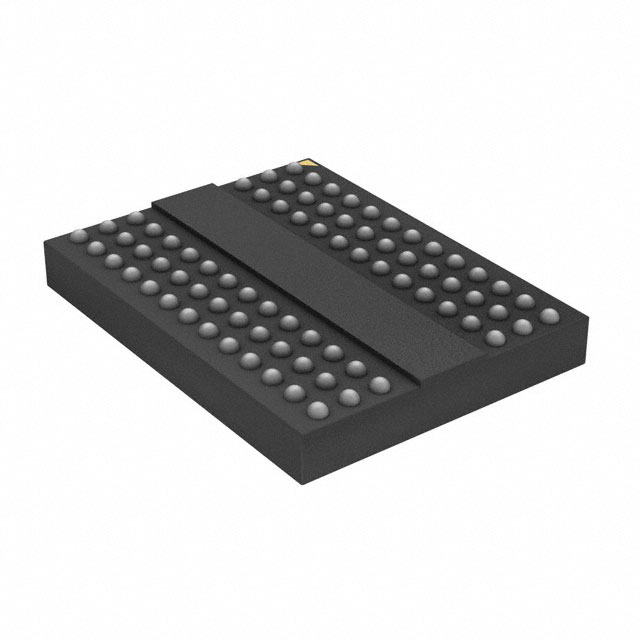
Figure 4: 78-Ball FBGA – x8 (RH)
0.155
Seating plane
A
78X Ø0.45
Dimensions apply
to solder balls postreflow on Ø0.35 SMD
ball pads.
0.12 A
1.8 CTR
Nonconductive
overmold
Ball A1 ID
(covered by SR)
9
8
7
3
2
Ball A1 ID
1
A
B
C
D
E
F
10.5 ±0.1
G
9.6 CTR
H
J
K
L
M
N
0.8 TYP
0.8 TYP
1.1 ±0.1
6.4 CTR
0.25 MIN
9 ±0.1
Notes:
PDF: 09005aef85bd2a38
4Gb_auto_1_35v_ddr3l_rs.pdf - Rev. A 6/14 EN
1. All dimensions are in millimeters.
2. Solder ball material: SAC305 (96.5% Sn, 3% Ag, 0.5% Cu).
9
Micron Technology, Inc. reserves the right to change products or specifications without notice.
© 2014 Micron Technology, Inc. All rights reserved.
�4Gb: x8, x16 Automotive DDR3L-RS SDRAM
Package Dimensions
Figure 5: 96-Ball FBGA – x16 (HA)
0.155
Seating plane
96X Ø0.45
Dimensions
apply to solder
balls post-reflow
on Ø0.35 SMD
ball pads.
1.8 CTR
Nonconductive
overmold
9
8
7
3
A
2
0.12
A
Ball A1 Index
(covered by SR)
1
Ball A1 Index
A
B
C
D
E
F
G
H
12 CTR
J
14 ±0.1
K
L
M
N
P
R
0.8 TYP
T
1.1 ±0.1
0.8 TYP
6.4 CTR
0.25 MIN
9 ±0.1
Notes:
PDF: 09005aef85bd2a38
4Gb_auto_1_35v_ddr3l_rs.pdf - Rev. A 6/14 EN
1. All dimensions are in millimeters.
2. Solder ball material: SAC305 (96.5% Sn, 3% Ag, 0.5% Cu).
10
Micron Technology, Inc. reserves the right to change products or specifications without notice.
© 2014 Micron Technology, Inc. All rights reserved.
�4Gb: x8, x16 Automotive DDR3L-RS SDRAM
Electrical Characteristics – IDD Specifications
Electrical Characteristics – IDD Specifications
Table 5: IDD Maximum Limits – Die Rev. E
Speed Bin
Parameter
DDR3L-RS
-1066
DDR3L-RS
-1333
DDR3L-RS
-1600
DDR3L-RS
-1866
x4,x8
44
47
55
58
mA
1
x16
55
58
66
69
mA
1
x4
53
57
61
65
mA
1
x8
59
62
66
70
mA
1
Symbol Width
Unit Notes
Operating current 0: One bank
ACTIVATE-to-PRECHARGE
IDD0
Operating current 1: One bank
ACTIVATE-to-READ-to-PRECHARGE
IDD1
x16
80
84
87
91
mA
1
Precharge power-down current:
Slow exit
IDD2P0
All
12
12
12
12
mA
1
Precharge power-down current:
Fast exit
IDD2P1
All
24
26
30
35
mA
1
Precharge quiet standby current
IDD2Q
All
22
24
27
30
mA
1
Precharge standby current
IDD2N
All
22
24
26
29
mA
1
Precharge standby ODT current
IDD2NT
x4, x8
27
30
34
37
mA
1
x16
30
34
37
40
mA
1
Active power-down current
IDD3P
All
27
30
33
36
mA
1
Active standby current
IDD3N
x4, x8
29
32
35
38
mA
1
x16
37
40
43
46
mA
1
x4
105
122
139
160
mA
1
x8
115
132
149
170
mA
1
x16
176
193
227
244
mA
1
x4
80
95
110
125
mA
1
x8
87
103
118
133
mA
1
x16
129
144
163
186
mA
1
Burst read operating current
IDD4R
Burst write operating current
IDD4W
Burst refresh current
IDD5B
All
221
224
231
238
mA
1
Room temperature self refresh
IDD6
All
3.5
3.5
3.5
3.5
mA
2
+45°C temperature self refresh
IDD6A
All
3.7
3.7
3.7
3.7
mA
3
Elevated temperature self refresh
IDD6
All
7
7
7
7
mA
4
All
8.5
8.5
8.5
8.5
mA
5
Extended temperature self refresh
IDD6ET
All
14
14
14
14
mA
6
All
18
18
18
18
mA
7
All banks interleaved read current
IDD7
x8
152
182
213
243
mA
1
194
213
239
266
Reset current
IDD8
Notes:
PDF: 09005aef85bd2a38
4Gb_auto_1_35v_ddr3l_rs.pdf - Rev. A 6/14 EN
1.
2.
3.
4.
5.
x16
all
IDD2P0 + 2mA IDD2P0 + 2mA IDD2P0 + 2mA IDD2P0 + 2mA
mA
1
mA
1
TC = +85°C; SRT is disabled, ASR is disable. Value is maximum.
Room Temperature; SRT is disabled, ASR is enabled. Value is typical.
TC ≤ +45°C; SRT is disabled, ASR is enabled). Value is typical.
TC = +80°C; SRT is disabled, ASR is enabled). Value is typical.
+45°C < TC ≤ +80°C; SRT is disabled, ASR is enabled. Value is maximum.
11
Micron Technology, Inc. reserves the right to change products or specifications without notice.
© 2014 Micron Technology, Inc. All rights reserved.
�4Gb: x8, x16 Automotive DDR3L-RS SDRAM
Electrical Characteristics – IDD Specifications
6. TC = +95°C; SRT is disabled, ASR is enabled. Value is typical.
7. +85°C < TC ≤ +95°C; SRT is disabled, ASR is enabled. Value is maximum.
PDF: 09005aef85bd2a38
4Gb_auto_1_35v_ddr3l_rs.pdf - Rev. A 6/14 EN
12
Micron Technology, Inc. reserves the right to change products or specifications without notice.
© 2014 Micron Technology, Inc. All rights reserved.
�4Gb: x8, x16 Automotive DDR3L-RS SDRAM
Temperature-Compensated Self Refresh (TCSR)
Temperature-Compensated Self Refresh (TCSR)
The temperature-compensated self refresh (TCSR) feature substantially reduces the self
refresh current (IDD6). TCSR takes effect when T C is less than 45°C and the auto self refresh (ASR) function is enabled. ASR is required to utilize the TCSR feature and is enabled manually via mode register 2 (MR2[6]). See Figure 6 (page 13).
Enabling ASR also automatically changes the DRAM self refresh rate from 1x to 2x when
the case temperature exceeds 85°C. This allows the user to operate the DRAM beyond
the standard 85°C limit, up to the optional extended temperature range of 95°C while in
self refresh mode.
When ASR is disabled and T C is 0°C to 85°C, the self refresh mode refresh rate is assumed to be at the normal rate (sometimes referred to as 1x refresh rate). Also, if ASR is
disabled and T C is 85°C to 95°C, the user must select the SRT extended temperature self
refresh rate (sometimes referred to as 2x refresh rate). SRT is selected via mode register 2
(MR2[7]) register. See Figure 6 (page 13).
SPD settings should always support 05h (101 binary) in byte 31.
Mode Register 2 (MRS)
Mode register 2 (MR2) controls additional functions and features not available in the
other mode registers. The ASR function is of particular interest for the DDR3L-RS
SDRAM because the Micron DDR3L-RS SDRAM goes into TCSR mode when ASR has
been enabled. This function is controlled via the bits shown in the figure below.
Figure 6: Mode Register 2 Definition
BA2 BA1 BA0 A13 A12 A11 A10 A9 A8 A7 A6 A5 A4 A3 A2 A1 A0
Address bus
16 15 14 13 12 11 10 9 8 7 6
0 01 01 01 RTT(WR) 01 SRT ASR
Mode register 2 (MR2)
5
01 1
M15 M14
0
0
0
1
1
Mode Register
PDF: 09005aef85bd2a38
4Gb_auto_1_35v_ddr3l_rs.pdf - Rev. A 6/14 EN
3
M5 M4 M3
Mode register set 0 (MR0)
0
Normal (0°C to 85°C)
0
0
0
1
Mode register set 1 (MR1)
1
Extended (0°C to 95°C)
0
0
1
0
Mode register set 2 (MR2)
0
1
0
1
Mode register set 3 (MR3)
0
1
1
M10 M9
Note:
M7 Self Refresh Temperature
4
CWL
Dynamic ODT
(R TT(WR) )
0
0
RTT(WR) disabled
0
1
RZQ/4
1
0
RZQ/2
1
1
Reserved
2 1 0
01 01 01
CAS Write Latency (CWL)
5 CK (tCK ≥ 2.5ns)
6 CK (2.5ns > tCK ≥ 1.875ns)
7 CK (1.875ns > tCK ≥ 1.5ns)
1
0
0
8 CK (1.5ns > tCK ≥ 1.25ns)
9 CK (1.25ns > tCK ≥ 1.07ns)
1
0
1
10 CK (1.07ns > tCK ≥ 0.938ns)
M6
Auto Self Refresh
(Optional)
1
1
0
Reserved
0
Disabled: Manual
1
1
1
Reserved
1 Enabled: Automatic
1. MR2[17, 14:11, 8, and 2:0] are reserved for future use and must all be programmed to 0.
13
Micron Technology, Inc. reserves the right to change products or specifications without notice.
© 2014 Micron Technology, Inc. All rights reserved.
�4Gb: x8, x16 Automotive DDR3L-RS SDRAM
Electrical Specifications
Electrical Specifications
Table 6: Input/Output Capacitance
Capacitance
Parameters
Symbol
DDR3L-800
DDR3L-1066
DDR3L-1333
DDR3L-1600
DDR3L-1866
Min
Max
Min
Max
Min
Max
Min
Max
Min
Max
Units
Single-end I/O: DQ, DM
CIO
1.5
2.5
1.5
2.5
1.5
2.3
1.5
2.2
1.5
2.1
pF
Differential I/O: DQS,
DQS#, TDQS, TDQS#
CIO
1.5
2.5
1.5
2.5
1.5
2.3
1.5
2.2
1.5
2.1
pF
Inputs (CTRL,
CMD,ADDR)
CI
0.75
1.3
0.75
1.3
0.75
1.3
0.75
1.2
0.75
1.2
pF
Table 7: DC Electrical Characteristics and Operating Conditions – 1.35V Operation
All voltages are referenced to VSS
Parameter/Condition
Symbol
Min
Nom
Max
Units
Notes
Supply voltage
VDD
1.283
1.35
1.45
V
1, 2, 3, 4
I/O supply voltage
VDDQ
1.283
1.35
1.45
V
1, 2, 3, 4
Notes:
1. Maximum DC value may not be greater than 1.425V. The DC value is the linear average
of VDD/VDDQ(t) over a very long period of time (for example, 1 sec).
2. If the maximum limit is exceeded, input levels shall be governed by DDR3 specifications.
3. Under these supply voltages, the device operates to this DDR3L specification.
4. Once initialized for DDR3L operation, DDR3 operation may only be used if the device is
in reset while VDD and VDDQ are changed for DDR3 operation (see Figure 7 (page 27)).
Table 8: DC Electrical Characteristics and Operating Conditions – 1.5V Operation
All voltages are referenced to VSS
Parameter/Condition
Symbol
Min
Nom
Max
Units
Notes
Supply voltage
VDD
1.425
1.5
1.575
V
1, 2, 3
I/O supply voltage
VDDQ
1.425
1.5
1.575
V
1, 2, 3
Notes:
PDF: 09005aef85bd2a38
4Gb_auto_1_35v_ddr3l_rs.pdf - Rev. A 6/14 EN
1. If the minimum limit is exceeded, input levels shall be governed by DDR3L specifications.
2. Under 1.5V operation, this DDR3L device operates in accordance with the DDR3 specifications under the same speed timings as defined for this device.
3. Once initialized for DDR3 operation, DDR3L operation may only be used if the device is
in reset while VDD and VDDQ are changed for DDR3L operation (see Figure 7 (page 27)).
14
Micron Technology, Inc. reserves the right to change products or specifications without notice.
© 2014 Micron Technology, Inc. All rights reserved.
�4Gb: x8, x16 Automotive DDR3L-RS SDRAM
Electrical Specifications
Table 9: Input Switching Conditions – Command and Address
Parameter/Condition
Input high AC voltage: Logic 1
Symbol
VIH(AC160)min
DDR3L-800/1066
DDR3L-1333/1600
DDR3L-1866
Units
1
160
160
–
mV
1
Input high AC voltage: Logic 1
VIH(AC135)min
135
135
135
mV
Input high AC voltage: Logic 1
VIH(AC125)min1
–
–
125
mV
Input high DC voltage: Logic 1
VIH(DC90)min
90
90
90
mV
Input low DC voltage: Logic 0
VIL(DC90)min
–90
–90
–90
mV
1
Input low AC voltage: Logic 0
VIL(AC125)min
–
–
–125
mV
Input low AC voltage: Logic 0
VIL(AC135)min1
–135
–135
–135
mV
Input low AC voltage: Logic 0
1
–160
–160
–
mV
Note:
VIL(AC160)min
1. When two VIH(AC) values (and two corresponding VIL(AC) values) are listed for a specific
speed bin, the user may choose either value for the input AC level. Whichever value is
used, the associated setup time for that AC level must also be used. Additionally, one
VIH(AC) value may be used for address/command inputs and the other VIH(AC) value may
be used for data inputs.
For example, for DDR3L-800, two input AC levels are defined: VIH(AC160),min and
VIH(AC135),min (corresponding VIL(AC160),min and VIL(AC135),min). For DDRL-800, the address/
command inputs must use either VIH(AC160),min with tIS(AC160) of 215ps or VIH(AC135),min
with tIS(AC135) of 365ps; independently, the data inputs may use either VIH(AC160),min or
VIH(AC135),min.
Table 10: Input Switching Conditions – DQ and DM
Parameter/Condition
Input high AC voltage: Logic 1
Input high AC voltage: Logic 1
Symbol
VIH(AC160)min
DDR3L-800/1066
DDR3L-1333/1600
DDR3L-1866
Units
1
160
160
–
mV
1
135
135
135
mV
VIH(AC135)min
1
Input high AC voltage: Logic 1
VIH(AC130)min
–
–
130
mV
Input high DC voltage: Logic 1
VIH(DC90)min
90
90
90
mV
Input low DC voltage: Logic 0
VIL(DC90)min
–90
–90
–90
mV
1
–
–
–130
mV
Input low AC voltage: Logic 0
VIL(AC135)min
1
–135
–135
–135
mV
Input low AC voltage: Logic 0
VIL(AC160)min1
–160
–160
–
mV
Input low AC voltage: Logic 0
Note:
VIL(AC130)min
1. When two VIH(AC) values (and two corresponding VIL(AC) values) are listed for a specific
speed bin, the user may choose either value for the input AC level. Whichever value is
used, the associated setup time for that AC level must also be used. Additionally, one
VIH(AC) value may be used for address/command inputs and the other VIH(AC) value may
be used for data inputs.
For example, for DDR3L-800, two input AC levels are defined: VIH(AC160),min and
VIH(AC135),min (corresponding VIL(AC160),min and VIL(AC135),min). For DDRL-800, the data inputs must use either VIH(AC160),min with tIS(AC160) of 90ps or VIH(AC135),min with tIS(AC135)
of 140ps; independently, the address/command inputs may use either VIH(AC160),min or
VIH(AC135),min.
PDF: 09005aef85bd2a38
4Gb_auto_1_35v_ddr3l_rs.pdf - Rev. A 6/14 EN
15
Micron Technology, Inc. reserves the right to change products or specifications without notice.
© 2014 Micron Technology, Inc. All rights reserved.
�4Gb: x8, x16 Automotive DDR3L-RS SDRAM
Electrical Specifications
Table 11: Differential Input Operating Conditions (CK, CK# and DQS, DQS#)
Parameter/Condition
Symbol
Min
Max
Units
Differential input logic high – slew
VIH,diff(AC)slew
180
N/A
mV
Differential input logic low – slew
VIL,diff(AC)slew
N/A
–180
mV
Differential input logic high
VIH,diff(AC)
2 × (VIH(AC) - VREF)
VDD/VDDQ
mV
Differential input logic low
VIL,diff(AC)
VSS/VSSQ
2 × (VIL(AC) - VREF)
mV
VSEH
VDDQ/2 + 160
VDDQ
mV
Single-ended high level for strobes
Single-ended high level for CK, CK#
Single-ended low level for strobes
VSEL
Single-ended low level for CK, CK#
VDD/2 + 160
VDD
mV
VSSQ
VDDQ/2 - 160
mV
VSS
VDD/2 - 160
mV
Table 12: Minimum Required Time tDVAC for CK/CK#, DQS/DQS# Differential for AC Ringback
DDR3L-800/1066/1333/1600
tDVAC
tDVAC
DDR3L-1866
tDVAC
tDVAC
tDVAC
Slew Rate (V/ns)
at
320mV (ps)
at
270mV (ps)
at
270mV (ps)
at
250mV (ps)
at
260mV (ps)
>4.0
189
201
163
168
176
4.0
189
201
163
168
176
3.0
162
179
140
147
154
2.0
109
134
95
105
111
1.8
91
119
80
91
97
1.6
69
100
62
74
78
1.4
40
76
37
52
55
1.2
Note1
44
5
22
24
1.0
Note1
Note1
Note1
Note1
Note1
2.0
200
213
200
205
2.0
200
213
200
205
1.5
173
190
178
184
1.0
120
145
133
143
0.9
102
130
118
129
0.8
80
111
99
111
0.7
51
87
75
89
0.6
13
55
43
59
0.5
Note 1
10
Note 1
18
2.0
165
113
95
2.0
165
113
95
1.5
138
90
73
1.0
85
45
30
0.9
67
30
16
0.8
45
11
Note1
0.7
16
Note1
–
0.6
Note1
Note1
–
0.5
Note1
Note1
–